
The commercial property inspection process requires experience, knowledge of commercial building design to meet safety and functional standards, and a structured and consistent methodology. The following case study describes a commercial kitchen inspection based on this approach.
This case study evaluates a commercial building with two cooking areas. The cooking areas are located in separate sections of the building with no air communication between them. Cooking areas in commercial buildings can refer to a small breakroom kitchen or commercial kitchen operations.
This property has commercial kitchen operations, with cooking equipment that produces grease and other byproducts. For this type of commercial kitchen operation, a Type I kitchen hood with sufficient exhaust and make-up air system should be installed.
The inspector followed the Type I Exhaust Hood Inspection Checklist which addressed the following:
- Identifying the type of hood of equipment to ensure it handles grease and other byproducts
- Verifying the presence of AHJ-required cleaning and inspection tags on hoods and fire safety equipment
- Verifying the presence of fire safety features, such as suppression systems and fire extinguishers that are designed for grease type fires
The following are the prerequisites for performing commercial kitchen inspections:
- Knowledge of how ventilation systems are interconnected
- The hazards of grease-producing equipment
- The emergency and safety design features of the kitchen equipment
For comprehensive training, refer to the Inspecting Commercial Kitchens Online Course for Commercial Property Inspectors.
Inspecting Kitchen One
Commercial Kitchen One underwent a routine inspection with the following observations:
- The floors were made of sealed concrete.
- The walls featured washable laminate.
- The ceilings had washable tiles.
- Two mini-split heat pumps were in use.
- There was a door separating the cooking area from the rest of the building.
- There were overhead doors leading to the loading dock.
- There were interior doors connecting the loading dock to the prep kitchen.
- There were interior doors connecting the prep kitchen to the main cooking area.
- All doors were found to be ajar or slightly opened.
The image below shows the view between the main cooking area facing the open overhead door that leads to the loading dock (Image 1).
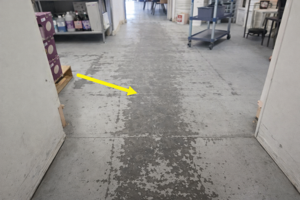
Image 1: View of the kitchen interior showing the main cooking area.
Main Cooking Area
On first pass, the main cooking area showed no obvious deficiencies (Image 2). However, a closer inspection is required to determine the condition of the kitchen and associated components for safety and proper operation.
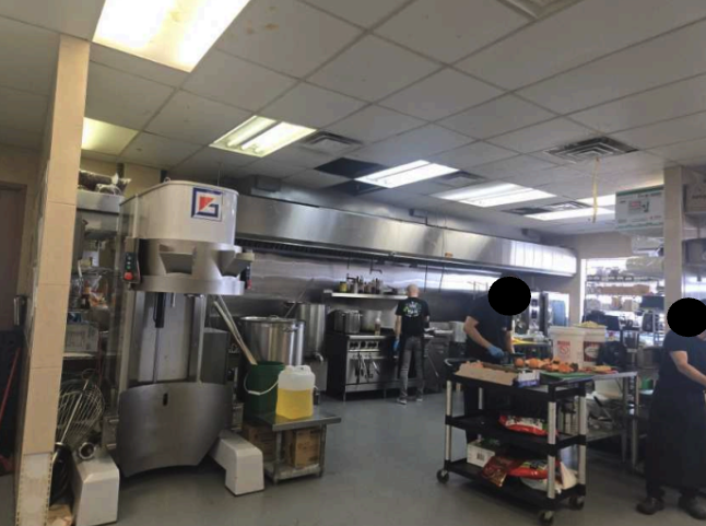
Image 2: View of main cooking area.
The main cooking area underwent a closer inspection with the following observations:
- The exhaust hood appeared to be in good physical condition meeting current design and manufacturer standards.
- No post-installation modifications were found to the exhaust hood that would invalidate its original design.
- The speciality labels were missing from the exterior side of the exhaust hood.
- Specialty labels refer to the manufacturer’s label, noting the type of hood in place (i.e., Type I or Type II).
- The cleaning labels were missing from the exterior side of the hood.
- Cleaning/inspection labels are placed on the hood after AHJ-required inspection. These labels identify the last time the hood was professionally cleaned and serviced.
- Some hoods may also have a permanent tag that defines performance related criteria.
Note: Additional AHJ required inspection/cleaning tags or labels may be affixed to other systems such as fire extinguishers, suppression canisters, and manual activator devices. The label on the hood specifically covers that component.
Exhaust Hood Inspection
This cooking area is situated above grease-producing appliances, therefore a Type 1 hood is needed. Type 1 hoods use filters known as baffles. Type 2 hoods use non-baffle style filters.
The following factors assess the ability of the hood to allow exhaust air and grease to effectively pass through the baffle filters, and protect the kitchen in the event of an emergency when fire suppression is expelled.
The Kitchen One exhaust hood underwent a closer inspection with the following observations:
- A Type 1 hood was identified (Image 3).
- The exhaust hood filters were baffle filters.
- The baffles were found to be installed vertically.
- The baffles were free of grease buildup.
- Suppression nozzles were positioned over the appliances.
- Blast-proof light fixtures were located underneath the hood.
- The exhaust fan and the fan control system were observed to be in good physical conditions with no visible signs of damage (Image 4).
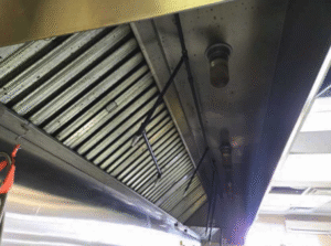
Image 3: View of the Hood Interior.
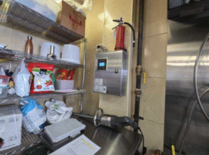
Image 4: View of the Fan Control System and Switch.
The following deficiencies were observed during the inspection.
Missing Life Safety System Components
The three essential components of the life safety system were not found, namely:
- A Type K fire extinguisher
- Fire suppression system canisters
- A manual actuator for the suppression systems
A Type ABC fire extinguisher was found resting on top of the fan control system. However, an ABC fire extinguisher is not effective at extinguishing grease fires. A type K fire extinguisher must be located within 30 feet of the cooking appliances.
Fire suppression system canisters are typically located next to the fan control system, in the ceiling, or within the exhaust hood system. The inspector used a ladder to help trace the fire suppression system (Image 5).
Tracing the plumbing is a useful technique when portions of the suppression system cannot be found, since all pipes in the system usually connect to a single source/location. There should be visible nozzles under the hood to where the plumbing exits the hood to where the suppression system tanks are located.
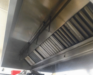
Image 5: Tracing the Pipes to Locate the Fire Suppression System.
The inspector traced the pipe to the end of the hood. At the end of the hood, the pipe should exit vertically through the hood up to the suppression tanks. However, no other plumbing or fire suppression tanks or systems were found at the exit of the hood. Instead, a connector where the pipes should be was found (Image 6).
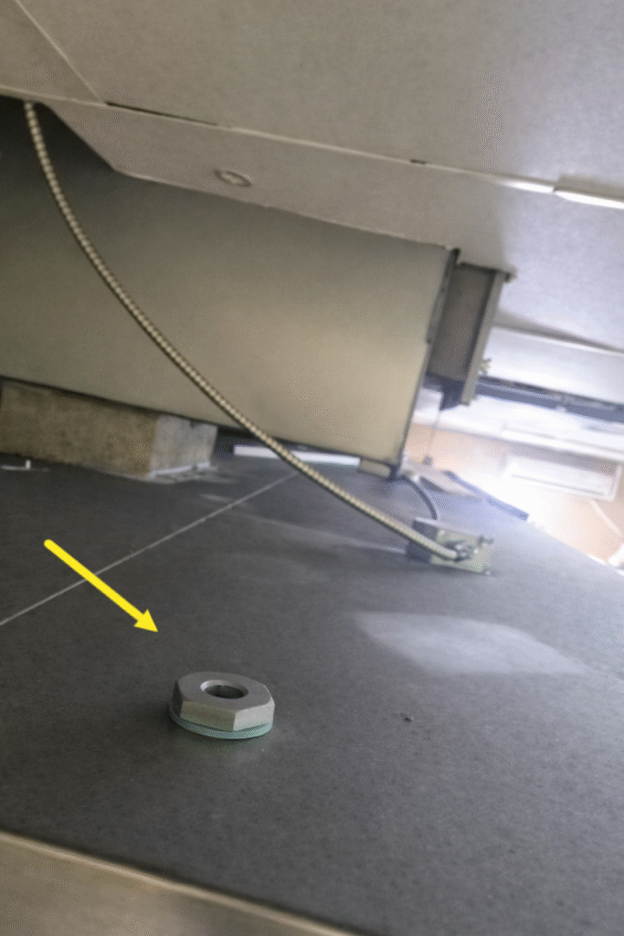
Image 6: View of the Top of the Hood and the Connector.
The suppression nozzles on this hood were never connected to a suppression system. Hence why the manual actuator was not found. Without a suppression system, there is no need for a manual actuator.
Missing Permanently Installed Vents or Ducts
There were no permanently installed vents or ducts found along the front of the hood.
The exhaust hood draws up large amounts of air to the outside. Vents or ducts should be permanently installed to provide make up / fresh air into the space to replenish what was removed by the exhaust hoods. Open tiles were noted in the ceiling during the inspection, but no permanently installed vents or ducts were present.
The exhaust hood was found to be in operation. Therefore, the inspector did not activate or cycle (turn on and off) the wall switch, nor did he request assistance from the workers to operate the exhaust hood.
A Deeper Look at the Make-Up Air Conditions
As previously mentioned, the cooking area was wide open. The doors connecting the large kitchen, the prep kitchen, and the loading dock were all open, allowing for unobstructed airflow. Given the issues found with the fire suppression system, it was anticipated that there might be problems with the make-up air system as well.
The roof of the building was not accessible, preventing the inspector from accessing the roof or any of its vent or duct systems. Therefore, the inspector used indirect inspection methods to determine if make-up air was being provided to the cooking area and exhaust system.
The inspector began closing each door one by one: first, the large overhead door, then the door between the loading dock and the prep kitchen, and finally, the door from the prep kitchen to the main cooking area. Each time a door was closed, it was drawn toward the main cooking area with increasing force. This behavior was a strong indication that the building did not have a make-up air system.
It appeared that the exhaust system was utilizing all of the open space and fresh air to compensate for the air being drawn up through the exhaust fan. When a door is closed, the air in that room is no longer available, creating a vacuum. Once the last door was closed, the exhaust system no longer had a source of fresh air, drawing it from wherever possible, including the heating system or other occupied spaces.
During colder months, the exterior doors remain closed. The exhaust system draws air as well as heat from the HVAC system. As a result, the HVAC system can no longer maintain the kitchen temperature at a comfortable level. Adding heat pumps was the simplest way for the building to provide extra heat without needing to add space heaters.
All exterior doors should open outward and should open quickly when a small to moderate force is applied, since it is a means of egress. With the exhaust hood system running and all other exterior doors closed, the inspector attempted to push open the exterior door. The inspector found that while the door opened, it required more force than when all the other doors in the building were also open. This indicated that the building was under a vacuum.
The inspector then opened the door slightly to create a small gap between the door and the frame, allowing a small amount of air to pass through. The inspector observed a significant rush of air being drawn through that gap, confirming that the cooking area lacked a make-up air system.
Reporting
Checklists help inspectors stay on task and mitigate omissions. They can be used to guide inspectors through systems they might not be familiar with and keep the most seasoned inspectors on target. The techniques used by these inspectors were largely visual. They did not provide any technically exhaustive measures. The inspector wrote the following comment on their inspection report:
“Issues are present in the cooking area that will require attention. A type K fire extinguisher was not present, and the suppression system was not installed, leaving the cooking area without any fire protection. The exhaust system does not appear to have a make-up air system. Make-up air systems may not be required in every cooking area, but as a result of the other conditions, we recommend further inspection and review by a qualified HVAC contractor to determine need.”
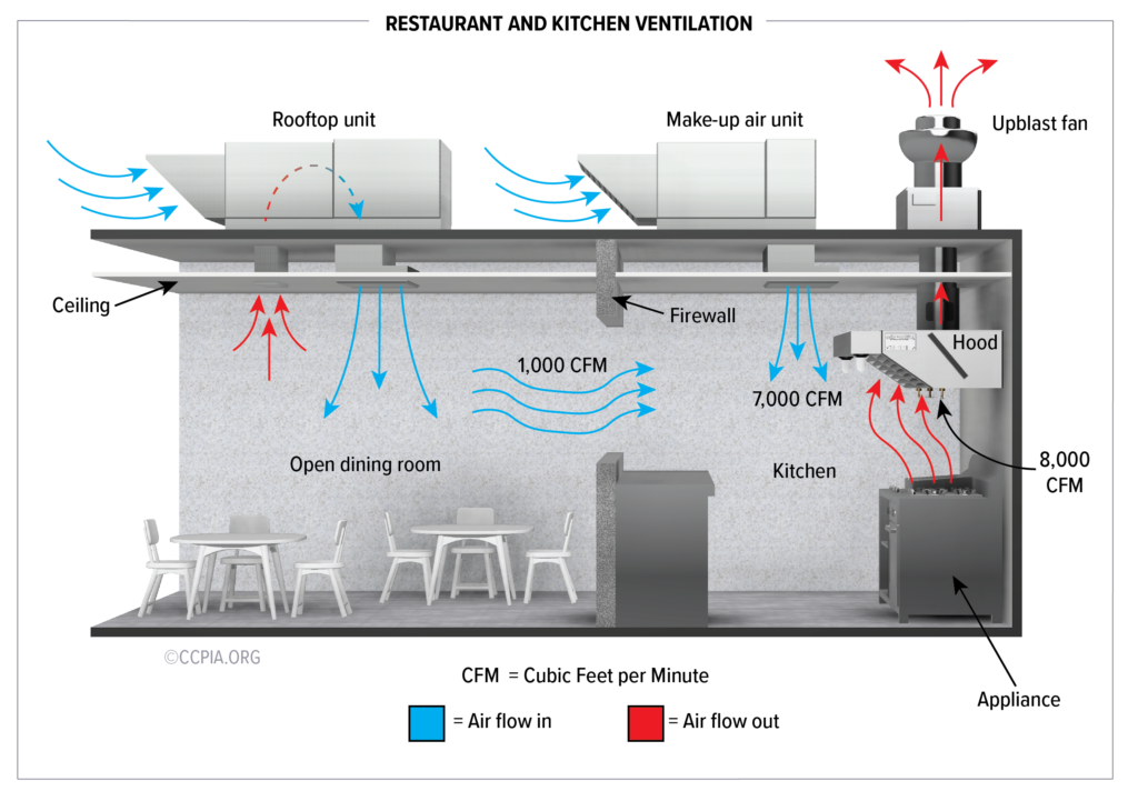
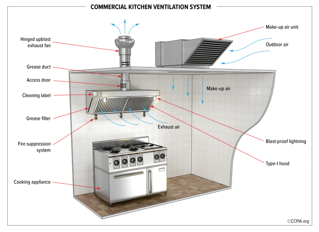
Use the following illustration, an understanding of how systems are interconnected, observed conditions, and a robust checklist to help guide inspections.
Inspecting Kitchen Two
Kitchen number two is located in the same building but in another wing (Image 7). The two kitchens do not share any common walls or HVAC systems. The inspector used the same checklists as for Kitchen One. The inspector was better prepared for this inspection knowing the significant safety issues observed with Kitchen One.
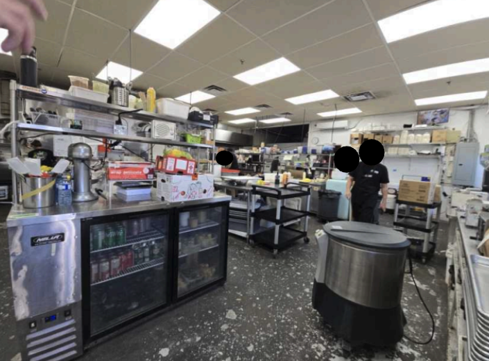
Image 7: View of Kitchen Two.
Commercial Kitchen Two underwent a routine inspection using the checklist with the following observations:
- The fire suppression canister was found on Kitchen Two’s exhaust hood (Image 8).
- The date on the canister was found to be expired.
- The manual actuator was located on the exhaust hood (Image 9).
- A type K fire extinguisher was located on the floor within 30 feet of the cooking equipment.
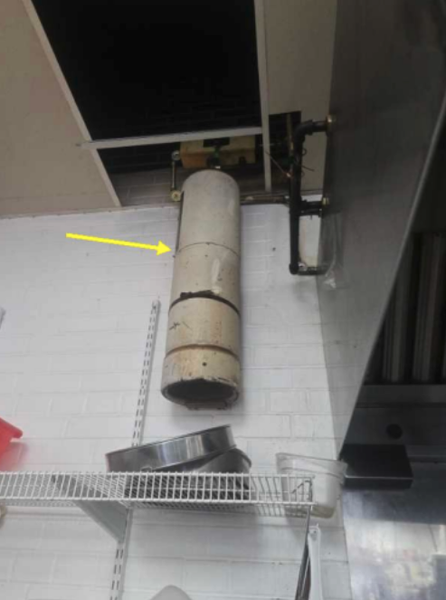
Image 8: View of the Suppression Tank.

Image 9: View of the Manual Actuator.
Exhaust Hood Inspection
The Kitchen Two exhaust hood underwent a closer inspection with the following observations:
- Two hoods were found separated by a 5-foot gap (Image 10)
- The following elements were found in the gap (Image 10):
- The manual actuator
- A refuse can
- A refrigerator
- A deep fat fryer (Image 11)
Type I hoods, also known as grease hoods, are designed to remove heat, smoke, condensation, and other grease byproducts of cooking. Not having the deep fat fryer under the Type 1 hood system leaves the fryer without fire protection and also prevents the grease from being captured by the system. Type 1 hoods should be installed above grease-producing equipment, such as cooktops, deep fryers, griddles, woks, charbroilers, and open-flame stoves; a Type II hood does not suffice.
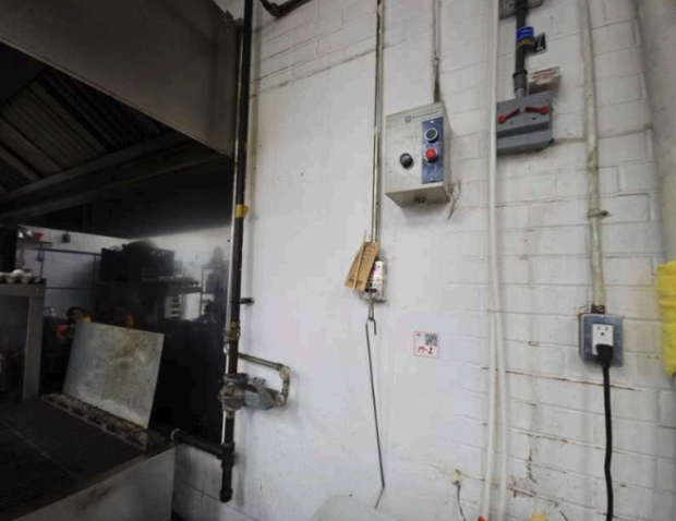
Image 10: View of the gap between the hoods.
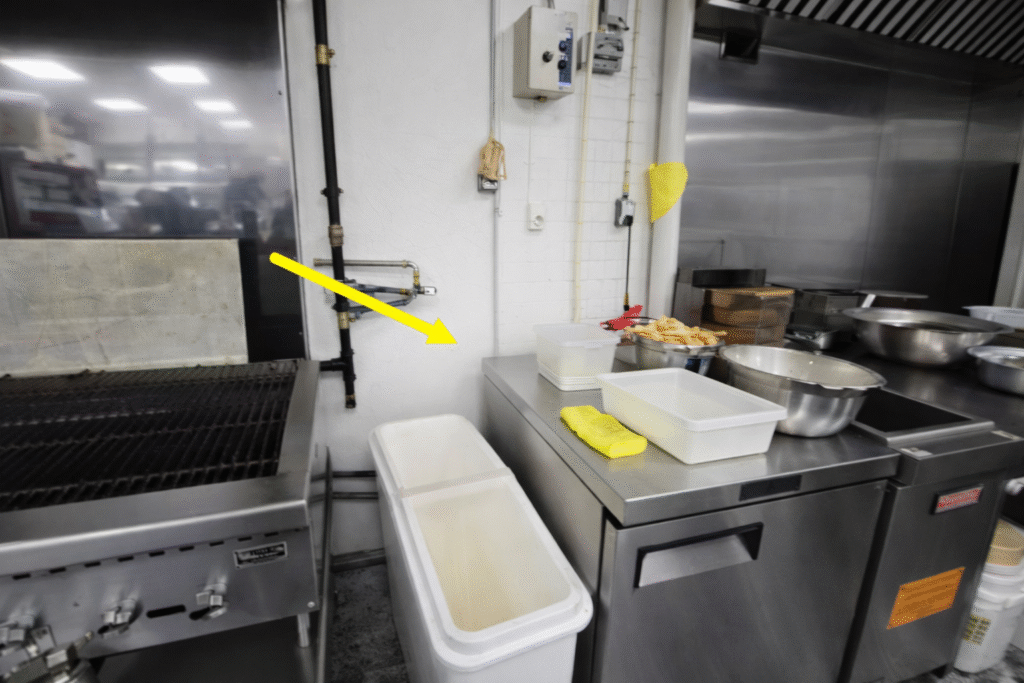
Image 11: The Deep Fat Fryer is located in the gap between the hoods.
The additional observations were made during the inspection:
- Baffles were identified in both hoods.
- The baffles had significant grease build up.
- The baffles showed signs of extensive damage (Image 12).
- Blast-proof light fixtures were found beneath both hoods.
- The covers to some of the lights were missing.
- Covers are designed to protect the blast-proof light fixtures.
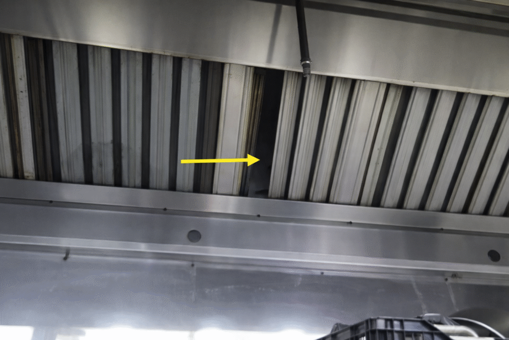
Image 12: View of Damaged Baffles.
Reporting
Kitchen Two shared some of the same issues as Kitchen One. Two separate report sections were created for each kitchen since there was sufficient separation between the two spaces. Combining the comments from both kitchens into one section would not accurately address the conditions and inform the client about the severity of the issues.
The inspector wrote the following comment about Kitchen Two:
“The suppression system for this kitchen was found to be out of date. The hood system is not located over or servicing all of the appliances in the kitchen, including a deep fat fryer located outside of the hood enclosure. Also, components of the hood were observed to have failed. There are broken light fixtures and damaged baffles. The exhaust system was also observed to have grease buildup present throughout all of the baffles and hood panels. Attention is strongly recommended.”
Use the following illustration, an understanding of how systems are interconnected, observed conditions, and a robust checklist to help guide inspections.
Conclusion
The purpose of the ComSOP (International Standards of Practice for Inspecting Commercial Properties) is to define best practices and establish a reasonable approach for inspecting commercial properties. The cooking area, or commercial kitchen, is often the main source of revenue for many businesses. However, the commercial kitchen can also pose significant safety hazards if not properly maintained or neglected. The Certified Commercial Property Inspectors Association has developed courses and checklists to help inspectors navigate these complex areas of a building, ensuring they provide thorough inspections for their clients.
Identifying safety issues during these inspections can help prevent catastrophic situations, such as fires. If a fire does occur, the installed systems may allow for quicker suppression before it spreads to other areas of the property. The current user of this cooking area was unaware of any safety conditions; they were simply focused on operating their business.